"Communication link failure" message is displayed
Solution: Check the crimping and continuity of the connector on PCB 12032 (ident J24) and connector on PCB 10005 (ident J14 or J13 or J12)Details : Refer Cable PS6
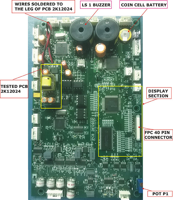
Solution: The two wires soldered to the leg of PCB 12024 are broken, solder them properly.Details : Photo of monitor PCB's - Image 3
Solution:The connector from DC-DC PCB 10005 (ident J14 Or J13 or J12) to the Parameter PCB 12032 (ident J24) faultly. Check voltage - 12v on the DC-DC PCB (10005). Place the multimeter probes on each of the connector pins. If it not coming change PCB 10005v5.Details : Refer Cable PS6;Also Refer Photo of monitor PCB's - Image 1 and Reference document for making changes in the unit
Alarm Buzzer not ringing
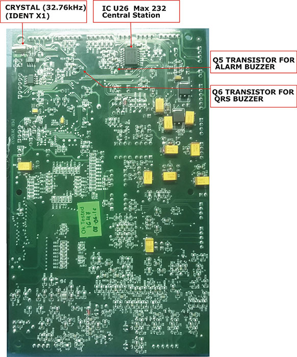
Solution:Touch up SMD transistor BC 547 (ident Q5) on solder side on PCB 12032Details : Photo of monitor PCB's - Image 4
Alarm LED does not glow
Solution:Check continuity of 3 pin relimate connector on PCB 12032 (ident J1) to 3 pin connector in Beta LED PCBDetails : Refer Cable FP4
Central Station communication problem
Solution:Check IC max 232 for dry solder on solder side on PCB 12032, (ident U26) touch up the ICDetails : Photo of monitor PCB's - Image 4
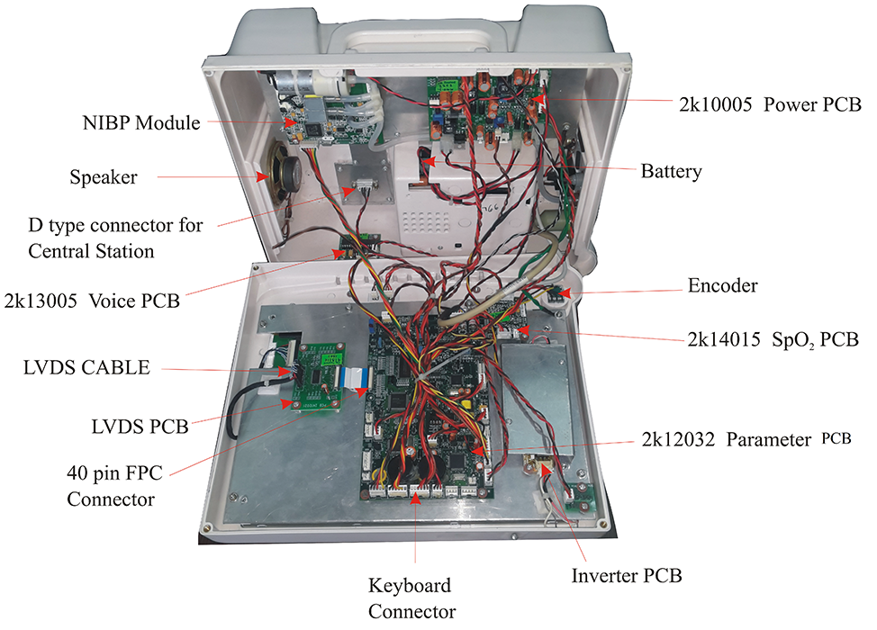
Solution:Check continuity of D type connector . The D type connector is on the back side of the MonitorDetails : Refer Cable SP7 and Photo of monitor PCB's - Image 1,Image 2
Display problem - Colour is changed, White display
Solution:Check 40 pin FPC cable is not connected properly, The cable connected from PCB 12032 (ident J21) to LVDS PCB 12021 (ident J9)Details : Reference document for making changes in the unit and Photo of monitor PCB's - Image 1
Solution:Touch up the resistor line form ident R222 to R233 on PCB 12032Details : Photo of monitor PCB's - Image 3
Solution:PCB 2K12032 (ident J21) 40 pin fpc connector is faulty replace it. Cable flat (fpc) 40 pin, 0.5mm ,length 4 inchDetails : Photo of monitor PCB's - Image 1
Display problem - No display
ECG traces are flat or missing
Solution:Panel mounting 6 pin ECG input connector on PCB 12032 (ident J2).Check continuity of ECG cable between side plate and PCB , If faulty replace.Details : Refer Cable SP1
Encoder not working
Solution:Check continuity of the encoder. If faulty resolder the wires or replace the encoderDetails : Refer Cable FP1 and Photo of monitor PCB's - Image 1
It turns ON in battery mode but not on Mains
Solution:Check the back panel fuse holders must be loose or the wrong fuse is inserted. (Fuse 5 amp slow blow 20mm, voltage rating - 250v)Details : NA
Keyboard not working
Solution:Check continuity between 6 pin relimate connector on PCB 12032 (ident J10) and 4 pin connector on the keyboardDetails : Refer Cable FP2 and Photo of monitor PCB's - Image 1
Monitor does not turn on
Solution:Check if fuse is inserted into the back panel (Fuse 5 amp slow blow 20mm, voltage rating - 250v)Details : NA
Solution:Check LED (ident D1) for indication if PCB is turning ON or not ; If the LED on the PCB is turning ON, then PCB is Ok. If the LED does not turn ON, then check continuity Check the input connector continuity (ident J1) on PCB 10004. If there is no conitniuty then replace the cableDetails : Refer Cable PS1 - Photo of monitor PCB's - Image 2
Solution:Check the PCB 10004 - The thermistor NTC 10ohm (ident NTC), Capacitor (ident MOV) could be burnt. Check and replaceDetails : Refer Photo of monitor PCB's -Image 2
Solution:Check the PCB 10004 - Regulator IC TOP 256 YN (ident U1) is shorted, check and replaceDetails : Refer Photo of monitor PCB's -Image 2
Solution:Check the continuity between 2 pin relimate connector (ident J11) on PCB 10005 to the Keyboard panelDetails : Refer Cable no FP3
NIBP READING changing
Solution:Check continuity of 6 pin reliamate (Para1005) on PCB 12032 (ident J5) 4 pin jst on lifeguard module (ident R1)Details : Refer Cable SP4
QRS, Pulse beep not ringing
Solution:Touch up SMD transistor BC 847 (ident Q6) on solder side of PCB 12032Details : Refer Photo of monitor PCB's - Image 4
SpO2 trace is flat
Solution:Check continuity of 4 pin relimate connector on PCB 12032 (ident J7) to 4 pin jst connector on PCB 14015 (ident P2)Details : Refer Cable SP2.2
Solution:Check continuity of the Spo2 connector (side panel of the monitor) to the PCB 2K14015Details : Refer Cable SP2.1
Time is 00:00
Solution:Coin cell battery 3V (next to buzzer) on PCB 12032 is faulty replace itDetails : Refer Photo of monitor PCB's - Image 3
Time is not updating
Solution:Crystal 32.76Khz (ident X1) on PCB 12032 is faulty, replace itDetails : Refer Photo of monitor PCB's - Image 4
Yellow ring of the SpO2 connector on the side panel is broken