Display colour changes
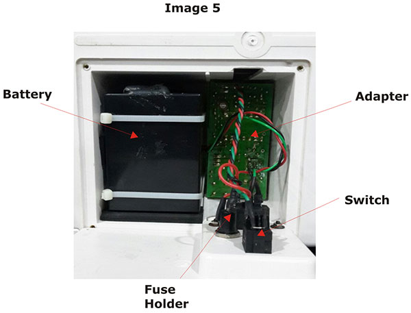
Solution: FPC cable connecting LCD to PCB 13002 (ident J14) is not connected properly. Replace the cable or connect it properly.Details : Refer reference document for making changes in the unit and Image 2
Does not turn ON on battery (after charging)
Solution:Solution :Check the voltage of the battery, if it less than 8v then replace the battery. Sealed lead acid battery 12v/4.5ah (size-90X70X101mm).Details : Refer reference document for making changes in the unit and Image 5
ECG traces are flat
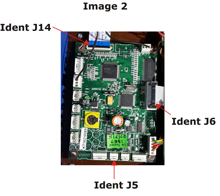
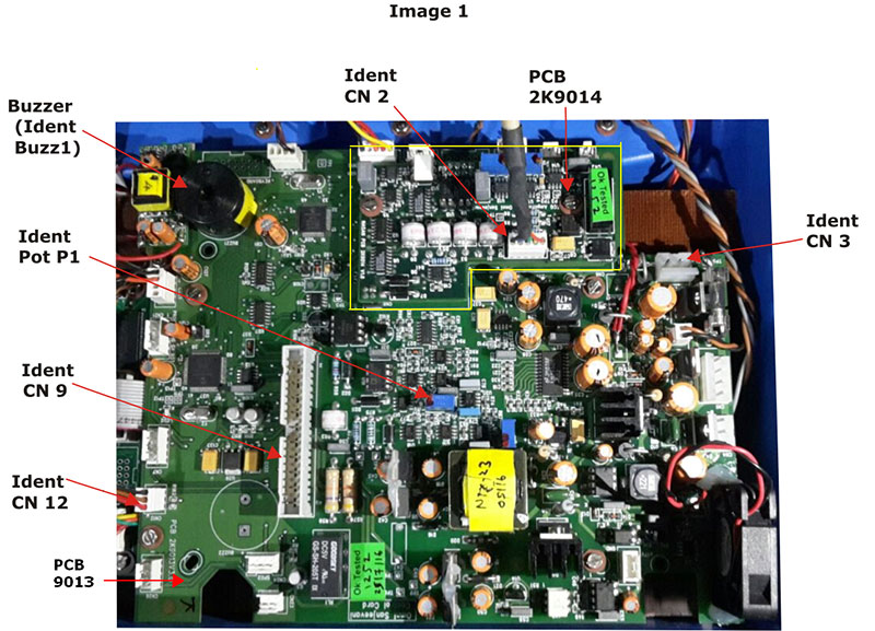
Solution:Check crimping and continuity of ECG connector from PCB 9014 (ident CN2) to the side panel of the unit.Details : Refer Cable SP1 and Image 1
Solution:Change PCB 9014 - ECG amplifier.Details : Refer reference document for making changes in the unit and Image 1
Encoder broken
Solution:Check the encoder, If broken replace it .(Encoder - encoder pec16-4220f-s0012; 20MM SHAFT w/switch).Details : Refer Cable FP3
It does not give 'PAPER OUT' message
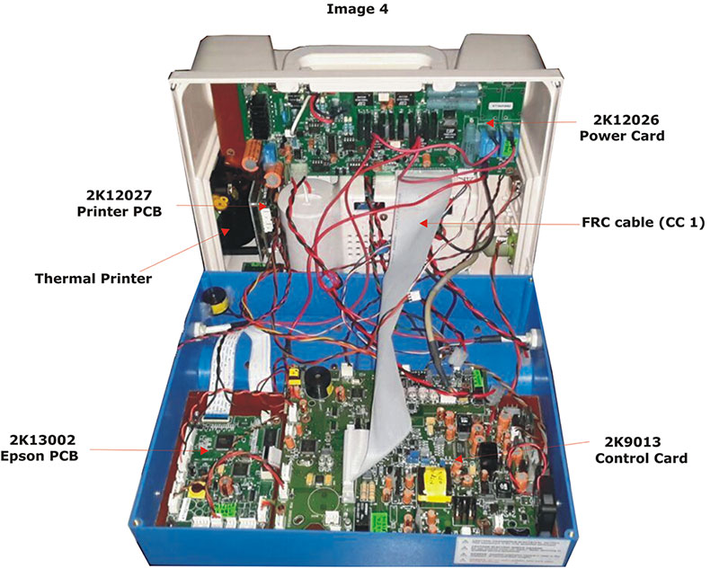
Solution:Flex cable of the printer not connected properly to PCB 12027 (ident J2). Check and connect it properly.Details : Refer Document A1 and Image 4
Solution:If Flex cable is connected properly then check the printer (check with new printer).Details : Refer Document A1
Solution:Change PCB 12027 - Printer PCB.Details : Refer reference document for making changes in the unit and Image 4
Keyboard not working
Solution:Replace keyboard and check it. The FRC cable is connected to PCB 13002.Details : Refer Document A2
Solution:Replace PCB 13002 and check it. The FRC cable is connected to PCB 13002.Details : Refer reference document for making changes in the unit and Image 2
Keys on keyboard not working
Solution:Replace keyboard. The FRC cable of the keyboard is connected to PCB 13002.Details : Refer Document A2
Mains-Batt indication is not glowing
Solution:Check continuity of 3 pin relimate connector on PCB 13002 (ident J5) to 3 pin relimate connector on PCB 9013 (ident CN12) , if faulty replace it.Details : Refer Cable CC4
Solution:If the cable CC4 is not faulty then replace keyboard.Details : Refer Document A2
Manual check process is not completed
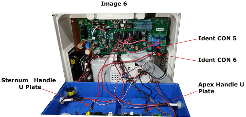
Solution:Check continuity of U plate connection from Apex handle to PCB 12026 (ident CON6), If faulty replace it.Details : Refer Cable FP8and Image 6
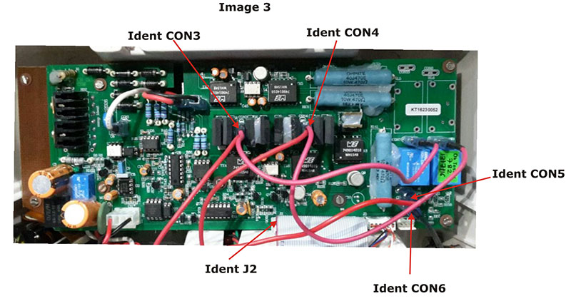
Solution:Check cable from Apex handle to PCB 12026 (ident CON3), If broken, replace it.Details : Image 3
Solution:Check continuity of U plate connection from Sternum handle to PCB 12026 (ident CON5), If faulty replace it. (ident CON3), If broken, replace it.Details : Refer Cable FP7 and Image 6
Solution:Check cable from Sternum handle to PCB 12026 (ident CON4). If broken, replace it.Details : Image 3
Manual check process is not completed (Only "Place pads in cradle" message is displayed)
Solution:Check if handle is placed properly in the cradle along with the adult plate. Remove the handle and place it in the cradle again.Details : NA
Solution:Check POT (ident Pot P1) on PCB 9013 or 14010 to 3.28v with respect to ground of (ident CN3) Handle should be placed in the cradle.Details :Refer Image 1
QRS Volume cannot be varied
Solution:Check the 100k linear pot, if faulty replace it.Details : Refer Cable FP2.1
Print out is blank.
Solution:Flex cable of the printer not connected properly to PCB 12027 (ident J2). Check and connect it properly.Details : Refer Document A1
Solution:If Flex cable is connected properly then check the printer (check with new printer).Details : Refer Document A1
Solution:Change PCB 12027 - Printer PCB.Details : Refer reference document for making changes in the unit and Refer Image 4 and Refer Document A1
Printer paper rolls in the opposite direction
Solution:Flex cable of the printer not connected properly to PCB 12027 (ident J2). Check and connect it properly.Details : Refer Document A1
Solution:If Flex cable is connected properly then check the printer (check with new printer).Details : Refer Document A1
Solution:Change PCB 12027 - Printer PCB.Details : Refer reference document for making changes in the unit and Refer Image 4 and Refer Document A1
QRS volume not coming
Solution:Solution :Check the 100k linear pot, if faulty replace it.Details : Refer Cable FP2.1
Solution:Check buzzer (B20) on PCB 9013 (ident Buzz 1) Control card, if faulty replace it.Details : Refer Image 1
Shock is not delivered
Solution:Solution :Check continuity of U plate connection from Apex handle to PCB 12026 (ident CON6), If faulty replace it.Details : Refer Cable FP8 and Refer Image 6
Solution:Check continuity from Apex handle to PCB 12026 (ident CON3), If faulty replace it.Details : Refer Image 3
Solution:Check continuity of U plate connection from Sternum handle to PCB 12026 (ident CON5), If faulty replace it.Details : Refer Cable FP7 andRefer Image 6
Solution:Check continuity from Sternum handle to PCB 12026 (ident CON4), If faulty replace it.Details : Refer Image 3
Solution:Check the corrosion on adult and child plate of the handle. If they are corroded replace them. The corrosion can affect the accuracy of shock delivery.Details : NA
Solution:Change FRC cable connecting PCB 9013 or PCB 14010 (ident CN9) to PCB 12026 (ident J2).Details : Refer Cable CC1 and Refer Image 4
SpO2 waveform is flat
Solution:Check continuity of Spo2 connector from PCB 9013 to PCB 14015, If faulty replace it.Details : Refer Cable SP2.2
Solution:Check continuity of Spo2 connector from PCB 14015 to side panel of the unit, If faulty replace it.Details : Refer Cable SP2.1
Solution:Change PCB 14015 - SpO2 card.Details : Refer reference document for making changes in the unit
Unit does not turn ON
Solution:Check the switch on the front panel (green). If broken then replace it.Details : Refer Cable FP1 and Document A2
Unit does not turn 'ON' on Mains
Solution:Check if fuse is faulty or fuse holder is broken (On the back panel). If faulty replace it. Fuse should be 8 A. With voltage rating of 250v.Details : NA
Solution:Check adaptor output, on PCB 9013(ident CN3). It should be 17v. Check with respect to pin no 1(output) and 3(ground). If it is less than 17v then, replace the adaptor.Details :Refer Image 1
Unit is not charging
Solution:Change FRC cable connecting PCB 9013 (ident CN9) PCB 12026 (ident J2).Details : Refer Cable CC1 and Refer Image 4
Solution:Check if the unit is charging using 'Charge' button on the Apex handle. If yes then the Blue charge switch on the front panel may be faulty, replace it.Details : Refer Cable FP10 and Document A2
Voice does not sound proper
Solution:Physically check the speaker, if broken replace it.Details : NA
Voice Volume cannot be varied