"Communication link failure" message is displayed
Solution: Check the crimping and continuity of the connector on PCB 12032 (ident J24) and connector on PCB 10005 (ident J14 or J13 or J12)Details : Refer Cable PS6
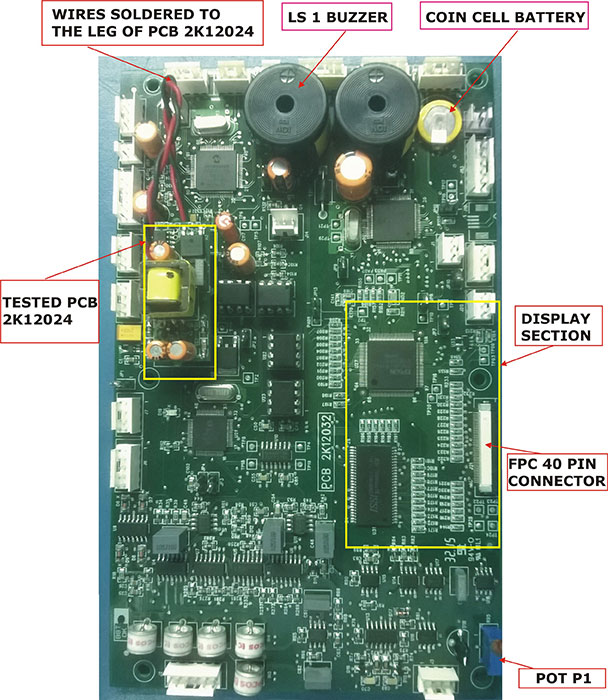
Solution: The two wires soldered to the leg of PCB 12024 are broken, solder them properly.Details : Photo of monitor PCB's - Image 3
Solution:The connector from DC-DC PCB 10005 (ident J14 Or J13 or J12) to the Parameter PCB 12032 (ident J24) faultly. Check voltage - 12v on the DC-DC PCB (10005). Place the multimeter probes on each of the connector pins. If it not coming change PCB 10005v5.Details : Refer Cable PS6;Also Refer Photo of monitor PCB's - Image 1 and Reference document for making changes in the unit
Alarm Buzzer not ringing
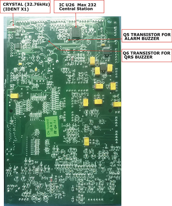
Solution:Touch up SMD transistor BC 547 (ident Q5) on solder side on PCB 12032Details : Photo of monitor PCB's - Image 4
Alarm LED does not glow
Solution:Check continuity of 3 pin relimate connector on PCB 12032 (ident J1) to 3 pin connector in Beta LED PCBDetails : Refer Cable FP4
Central Station communication problem
Solution:Check IC max 232 for dry solder on solder side on PCB 12032, (ident U26) touch up the ICDetails : Photo of monitor PCB's - Image 4
Solution:Replace the IC Max 232 on PCB 12032, (ident U26)Details : Photo of monitor PCB's - Image 4
Solution:Check continuity of D type connector . The D type connector is on the back side of the MonitorDetails : Refer Cable SP7 and Photo of monitor PCB's - Image 1
Display problem - Colour is changed, White display
Solution:Check 40 pin FPC cable is not connected properly, The cable connected from PCB 12032 (ident J21) to LVDS PCB 12021 (ident J9)Details : Reference document for making changes in the unit and Photo of monitor PCB's - Image 1
Solution:Touch up the resistor line form ident R222 to R233 on PCB 12032Details : Photo of monitor PCB's - Image 3
Solution:PCB 2K12032 (ident J21) 40 pin fpc connector is faulty replace it. Cable flat (fpc) 40 pin, 0.5mm ,length 4 inch Refer Photo of monitorDetails : Photo of monitor PCB's - Image 1
Display problem - No display
ECG traces are flat or missing
Solution:Panel mounting 6 pin ECG input connector on PCB 12032 (ident J2).Check continuity of ECG cable between side plate and PCB , If faulty replace.Details : Refer Cable SP1
Encoder not working
Solution:Check continuity of the encoder. If faulty resolder the wires or replace the encoderDetails : Refer Cable FP1
It turns ON in battery mode but not on Mains
Solution:Check the back panel fuse holders must be loose or the wrong fuse is inserted. (Fuse 5 amp slow blow 20mm, voltage rating - 250v)Details : NA
Keyboard not working
Solution:Check continuity between 6 pin relimate connector on PCB 12032 (ident J10) and 4 pin connector on the keyboardDetails : Refer Cable FP2
Monitor does not turn on
Solution:Check if fuse is inserted into the back panel (Fuse 5 amp slow blow 20mm, voltage rating - 250v)Details : NA
Solution:Check the continuity between 2 pin relimate connector (ident J11) on PCB 10005 to the Keyboard panelDetails : Refer Cable no FP3
NIBP READING changing
Solution:Check continuity of 6 pin reliamate (Para1005) on PCB 12032 (ident J5) 4 pin jst on lifeguard module (ident R1)Details : Refer Cable SP4
QRS, Pulse beep not ringing
Solution:Touch up SMD transistor BC 847 (ident Q6) on solder side of PCB 12032Details : Refer Photo of monitor PCB's - Image 4
SpO2 trace is flat
Solution:Check continuity of 4 pin relimate connector on PCB 12032 (ident J7) to 4 pin jst connector on PCB 14015 (ident P2)Details : Refer Cable SP2.2
Solution:Check continuity of the Spo2 connector (side panel of the monitor) to the PCB 2K14015Details : Refer Cable SP2.1
Time is 00:00
Solution:Coin cell battery 3V (next to buzzer) on PCB 12032 is faulty replace itDetails : Refer Photo of monitor PCB's - Image 3
Time is not updating
Solution:Crystal 32.76Khz (ident X1) on PCB 12032 is faulty, replace itDetails : Refer Photo of monitor PCB's - Image 4
Yellow ring of the SpO2 connector on the side panel is broken